This is a repair for a GD-TT2 whose “POWER TRAIN” light came on while driving.
A memory read check revealed diagnosis code “22.”
A D check also revealed diagnosis code “22,” so it doesn’t seem to be a temporary issue.
Diagnosis code “22” is defined as “Knock sensor system: open/short.”
A short suggests a sensor failure or a wiring error.
An open suggests a sensor failure or a wiring error, particularly a loose connector connection. Perhaps?
Since the error appeared during a test drive after reassembly, it seems more realistic to consider improper assembly rather than a component failure.
So, I started by checking the wiring.
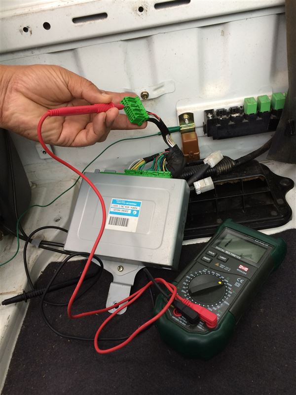
I removed the driver’s seat, disconnected the ECU, and unplugged the connector (22P).
The white cord connected to pin 5 of the connector (22P) identified as “R134” on the circuit diagram is the knock sensor signal wire.
The knock sensor appears to be a piezoelectric element that generates a voltage signal connected to the body ground.
When I checked the continuity between pin 5 of “R134” and the body ground, it appeared to be open.
If that’s the case, I suspect a fault or break somewhere in the wiring from the sensor to “R134.”
There are two connector connections between the sensor and the ECU: connector “E5” at the sensor, and connector “R100” at the connection between the engine harness and body harness.
I decided to check for breaks in the sections separated by each connector.
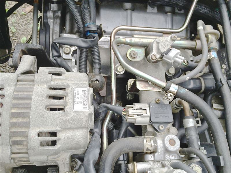
The knock sensor is located directly below the intake manifold.
In the photo, you can see the knock sensor below the intake manifold, but it is hard to see and hard to reach.
If you look under the intake manifold, you can see the knock sensor.
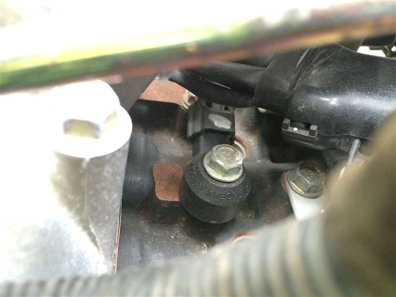
The black bolted part in the center of the photo is the knock sensor.
To completely remove the intake manifold, you would also need to remove the coolant piping, which would require draining the coolant, then refilling it later, and bleeding the air, which is a hassle.
So, as a compromise, I removed the intake manifold’s mounting bolts with the coolant piping still connected, lifted it from the engine, and reached into the gap to check the knock sensor wiring.
I removed connector “E5” from the sensor and checked the continuity between it and pin 5 of “R134” just before the ECU, and sure enough, it was open.
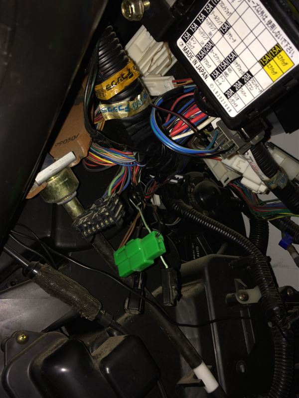
I tried to separate connector “R100” where the engine harness and body harness connect, and check the continuity of each of the two separated sections, but the area was too complicated and narrow to fit a probe, so I gave up.
I reconnected R100 and checked the continuity between E5 and R134 again, and this time there was continuity.
It seems that R100 was not connected properly.
I would have liked to check the condition of the sensor as well, but it would be difficult to reach and remove it, and even if I could remove it, I wouldn’t know how to determine whether it was OK or not, so I decided to just perform a D-check.
The D-check came back OK, so I think I’ve ruled out the cause of the POWER TRAIN light coming on.
After a test drive, refueling, and some shopping, I drove around 50km and everything was going great.
It was a long procedure that started with removing the engine, but it looks like the engine replacement work is now truly complete.
Comments